Friday, November 5, 2010

Research Experiment: FINAL TUTORIAL VIDEO

Attachment and Detachment of Numerous Independently Moving Entities

NOTE: HIGHLY RECOMMENDED TO VIEW FULL SCREEN AT 1080P HD.

The final version of my video tutorial regarding the attachment and detachment of various independently moving entities is presented above for final submission. The video has been separated into 4 key stages; the demonstration cubes formation, the setting out of the rotation points and mechanism, the setting out of the skeleton and its related operations and finally the attachment between the skeleton and the rotating mechanism. For further ease of understanding and convenience each flow graph is presented at the beginning of the tutorial as well as a table of content outlining when each stage of the tutorial begins. Finally I have attempted to present the tutorial with a sense style to engage the responder visually.

Research Experiment: 500 WORD TUTORIAL STATEMENT

With regards to the intention of my video tutorial regarding the application of flow graph nodes within a unique and interesting manner I decided to develop the notion of attaching and detaching individually and independently moving uniform entities. Through developed research I have discovered that there is serve lack of information and tutorials regarding complex operations of numerous entities management. Thus through my tutorial will the responder be presented with a manner in managing and controlling numerous entities within the field of rotation.

The tutorial subject is classified as advanced and portrays such through the formation of basically a Rubik’s cube within the Sandbox Editor requiring the responder to have a basic understanding of the program. The technique used involves the formation of an invisible skeleton (which at the beginning is visible to allow for set up) which moves around the exterior of the main cube, checking upon a key press whether the cube beneath is in the correct position for attachment. If true it attaches if false it does not. Such allows for individual entities to be managed within a larger overall state.

With regards to the body of information at which my video tutorial influences I wished to explore simply the field of as stated advanced entity management. Research upon the general internet and more specifically, Cry Wiki, CryMod and You Tube has presented it to be quite clear that there is limited information within this field as currently there only exists basic information on such as attaching an entity to the local player. Through my tutorial I will fill in the body of knowledge comprehensively and in a manner which will allow the individual to adapt the concepts presented in their own manner, thus meaning my tutorial will not only present a single notion and concept but rather provide a gateway to extendable knowledge achieved through individuals interaction, perception and adaptations of my video tutorials concepts.

In terms of the presentation of my tutorial I have considered the options between verbal and written communication upon their various positive and negative aspects. In terms of verbal communication I identified the notion of direct connect as the individual is engaged by the voice of a real human. However when one outlines a very complex and detailed concept it is sometimes hard to follow and keep up with what they are presenting. While written tutorials although not necessarily as in engaging allows the individual to pause the video at the various stages noting the concepts and processing them in their own time. Therefore I have decided to present my tutorial using written communication due to the complexity of my tutorial. The tutorial is divided into relative stages, upon were each stage is further divided into individual steps. Each series of steps is presented, before then the relative video for those steps is displayed while a small letter in the upper left hand corner alludes to the current step at which the video is up to within that stage.

EXP 2: FINAL POROSITY LENS DOCUMENTARY

- Depressions Complex Continuum -

NOTE: HIGHLY RECOMMENDED TO VIEW FULL SCREEN AT 1080P HD

Presented above is the final version of my porosity lens documentary for final submission. The documentary is titled “Depressions Complex Continuum” as it intends on outlining the manner in which an individual with depression interacts with their environment with reference to their mental state. The beginning of the documentary portrays an initially formed station which as the protagonist begins to simply walk through, changes becoming disordered from its original state, portraying the notion that individuals with depression through interaction may cause disorder within their own mental state and environment. While however as the documentary progresses the protagonist begins to run in the search for order within his environment and thus mental state. Such increased momentum alludes to the emotional state of anxiety related to depression while at the end when the protagonist eventually restores order, as presented through the re-formation of the original state of order upon the station, he remains suspended within his environment and thus depressions continuum, until eventually it consumes his entirety.

EXP 2: Final Sketch Up File

The link below presents the final Sketch Up file collaboration. It includes my custom installation together and separated, the modified station model together and separated, the installation and station together as a single unit and the station and installation separated with textures applied.

http://www.filefront.com/17478355/z3333170_BENV2423_EXP2_SketchUpComponents.skp

EXP 2: Final Crysis Levels and Object Files

The provided links below allow for the download of my levels folder and objects folder regarding Experiment Two. Note however due to the extreme complexity of final level concept, for filming purposes I was unable to film every series within one file due to that every computer I attempted such on either crashed and ran so slowly that fraps was basically just taking a series of stills. Therefore each take is separated into individual aspects of the three main journeys the protagonist portrays within the final documentary.

Levels Download:

http://www.filefront.com/17474172/z3333170_Crysis_Levels.zip

Objects Download:

http://www.filefront.com/17474197/z3333170_Objects.zip

Thursday, November 4, 2010

EXP 2: Week 7: Documentary Inspirations

- Inception Film Trailer -


The film inception is a prime example of the physical state of an environment I am attempting to achieve within my porosity lens documentary, especially as presented at the stage of 44 seconds in. It portrays perfectly the notion of an environment which is out of order and contorting to the interactions of the individuals. Through such strong and yet simple interactions is one able to study the manner in which those interactions alter the individuals environment, and more importantly there mental state, thus my porosity lens.

- This Mortal Coil -

The particular video above presents an interesting manner of emotional portrayal. It effectively stimulates the related emotions to the content of the video through the use of audio and presentation. Something which I wish to achieve within my porosity lens in terms of presenting an emotionally depressive state. In particular I like the manner in which the video begins through the use of small captions to focus the attention of the responder, a technique which I may use myself.

- Sin City Trailer -


The video above presents an interesting presentation method enhancing the use of black and white through the use of high lightening colour. Through unique presentation filming views is the viewer stimulated to delve deeper into the meaning behind. Furthermore this particular video develops on portraying a depressive state as rain and light is used in association with a night sky to create an overall very gloomy and dark environment.

Sunday, October 31, 2010

EXP 2: Week 7: Research Continued...

Entity Rotation Fall Through Problem:
Upon further implementation of my porosity lens concept and testing I discovered that when an basic physics entity is rotated the enabling of collisions is disabled, thus one falls right through when walking on the surface. However after discussing the issue with a friend he suggested I try implementing a small physics impulse to reset the physics upon each frame. Furthermore after posting it within the forum, Russell suggested that rather using a basic physics entity I rather use a Geometric Entity. Upon testing this I discovered that this was the best solution due to the simplicity of it, as it allowed me to walk over any surface of the rotated entity. However due to time constraints I was unable to go through the long process of switching all 27 components to geometric entities before re positioning them, so rather I decided to portray my porosity lens through AI’s. This proved to work very well from an external filming point of view as well as first person due to the manner in which particular AI expressions are rather depressed, enhancing the persona of my documentary with reference to my porosity lens brief.

Camera Attachment to Protagonist:

Through previous camera research I discovered the manner in which one is able to control a camera using the flow graph to present the view in game mode, while I wished to further learn how to attach the camera’s view to a moving person. I discovered this through research, as all you need to do is set up the camera within track view as normal but with only one position set, ensuring the track view’s length runs for as long as you wish to record. From here you create the normal flow graph, adding the usual Entity: AttachChild set up to attach the camera to either the local player or an AI. Such is outlined below.

AI Path Experimentation:

In the discussion of using AI’s to portray my porosity lens documentary I realised that I would be required to learn how to operate AI paths which I was able to do so through some research. Simply one creates a path ensuring the snap to terrain is set, outlining the path before placing the AI you wish to have walk along it at the beginning. One should note that for such to work the AI paths ‘road’ setting must be turned off. From here you simply use the following flow graph to attach the AI to the path setting a trigger. I also discovered that I needed to refresh and generate AI navigations before running it to ensure it works.

EXP 2: Week 6: Research Continued...

Entity Rotation of 360 Degrees – Version Two:

Upon discussing my mastery videos with a tutor he noticed the method of 360 degree rotation that I was using and suggested I use a much simpler method as present below. Rather than performing the rotation in two phases with a time delay, rather Interpol a single degree every fame to the entities position through a key input. This worked perfectly as I was beginning to have issues with my own method as it would only work on two axis. However the new method required a lot more processing putting a large amount of pressure on the CPU slightly slowing down the level. However I remained to incorporate this method in the final mastery demonstration video. I have provided the flow graph below.

Track view Camera Management:

As I further begin to consider the final presentation of my porosity lens I am questioning whether to film the documentary externally or from first person. After considering this further I decided that part will be filmed externally and thus required me to learn how to do track view cameras. After researching this I discovered that it was simple and only involved the formation of a normal track view with an added ‘scene node’ line before creating a simple flow graph as outlined below. However due to the smooth motion capabilities of the camera I have decided to attempt to further attach the camera to the local player to present different perspectives. I have been unable to achieve this of yet, but will continue researching this into the future.

Entity Attachment and Detachment Experimentation Six:

In terms of achieving my porosity lens I started to become very doubtful this week as to whether the attachment and detachment would even be possible to correctly manage due to the many attempted and failed experimentations I had carried out. However thankfully Vinh this week provided what he thought to be the solution. It was a very bold concept which we both believed would solve all problems. He proposed having an invisible skeleton with a parent centre point and then 8 children points which would move together around the faces of the cubes through a ‘mouse’ node available through the plug-in system. Further, each of the children points would test to determine whether a the skeletons child point is at the same point of the cube beneath it, if the subtraction of positions equalled zero it would attach (however through further testing by myself this equal was replaced with a less then 1). If the resultant was false it would remain detached. The conceptual sketch is included below to as how this system would work.


Through rigorous testing of this solution I further realised that as it was going to be impossible to have the local player walking normally vertically and upside as the faces rotate, rather the two opposite faces would rotate as a solution. However this meant the skeleton would become complex with now 17 children points. However through testing this solution it worked perfectly, in controlling the individual attachment of entities within faces. I even attempted to slightly alter the main attachment flow graph by placing a Entities: InRange node in the place of the mathematics to simplify it, however this failed so I kept with the original concept. Furthermore I was unable to get the mouse click plug-in working so I intend on researching other methods. I have included the two related flow graphs below in terms of the attachment control and the skeleton movement.


Skeleton Movement


Attachment and Detachment Management

EXP 2: Mastery Three – Entity:GetPos


Note: Recommended to view in 1080p HD.

Within the third mastery demonstration video of experiment two regarding the flow graph node “Entity: GetPos” my intent was to portray its ability regarding the calculation of numerous positions for future applications of management. This has been achieved through the attachment notion of an invisible skeleton which moves around the parameter of the main cube, comparing two values to determine whether an entity is in range and required to be attached. Such is portrayed through the first half of the video, as although the rotational attachments may appear simple, upon each new revolution the invisible skeleton is checking each of the 24 surrounding cubes to determine which entities to attach to the central rotation point cube. Furthermore to enhance this, I have included within the second half of the video, the movement of the skeleton with cubes at the end placements of the ‘children’s’ arms. This collaboration truly portrays the true mastery of this node as it is being used not only by itself but rather as a much larger and more complexly involved process of management. The manner in which such is achieved is presented beneath.


The flow graph above controls the testing and attachment of entity’s with reference to the skeleton. A key input triggers the sourcing of the cubes and relative skeletons cubes position, subtracting them before checking to see whether the resultant is less than one unit, if true it attaches, if false it doesn’t.


This flow graph controls the movement of the invisible skeleton. A key input triggers a math counter to compare the current and desired position and rotation of the parent entity of the skeleton through Entity: GetPos nodes, adjusting the current to the desired position and rotation.

Saturday, October 30, 2010

EXP 2: Mastery Two – Entity:EntityPos


Note: Recommended to view at 1080p HD.

The mastery video demonstration beneath portrays the use of the Entity:EntityPos flow graph node to calculate the local players world co-ordinates to effectively define the rotation of numerous individual entities which are attached to central point cube. Through the use of an addition control system within the flow graph one is able to control the rotational axis as which the local player’s position influences. Such enables one to accurately control the rotational angle upon a single axis rather than upon all three. Furthermore one is able define the sensitivity of the rotation in relation to the local players movement upon each individual axis separately. The manner in which this is all achieved is portrayed beneath.

The following flow graph consists of three similar components with simply different values. The local player’s position if compared to the position of the rotation point cube, before the resultant is split into individual axis, and changed, upon when it is then multiplied by a set value for each axis. The resultant is run through logic gate, to check to see whether it is too be run depending upon a key input, if so the entity’s rotational value is altered accordingly. If not, the operation is stoped.

EXP 2: Mastery One – Entity:AttachChild


Note: Recommended to view at 1080p HD.
Within the mastery video above regarding the “Entity:AttachChild” node my intention was to portray the possibilities in the attachment and detachment of numerous individual entities, conveyed through the use of rotation. In total there are 24 individual cubes which surround a centre rotational point cube upon each layer, which are completely independent of each other, thus through the use of the defined flow graph node one is able to attach them individually yet simultaneously to the rotational point. The manner in which the attachment and detachment is managed as well as the rotational mechanism is presented beneath.

The flow graph above uses a key input to trigger the attachment of the child (graph entity) to the parent (basic entity 3) when held, and upon release to detach the child (graph entity).

The following flow graph uses a key input to add a single degree to the rotation of the graph entity’s position each frame until it reaches 360.

Friday, October 29, 2010

EXP 2: Week 6: Tutorial Draft Video - Version One


The draft video tutorial above presents the general presentation mechanism I wish to use regarding the use of slides to enhance the video content. The overall video will be broken down into individual stages, and further more into individual steps which will be first outlined before then being demonstrated. Further I have decided to include all the flow graphs used within the tutorial upon slides at the beginning of the video which the responder will be able to screen shot and save for later use. Finally I have decided to create the video in HD to avoid the annoyance of watching a tutorial and not being able to identify what the person is clicking and selecting.

EXP 2: Week 6: Interconnection of Custom Textures and Forms

Through the further development of my data representation concept within experiment two I have produced three custom textures to be placed upon the custom installation. To further develop the notion of using the data in a manner that the protagonist is able to directly interact with. I have chosen to focus upon the statistics regarding the general number of men, women and youth suffering with depression in Australia. I have therefore created very simplistic textures which represents each of them, dispersing them over my custom instillations 26 individual components with reference to the statistical data. Thus the individual components of the station and installation work as a three dimension point graph perhaps of the data which the protagonist and hence responder engages with, as one moves through the environment, portrayed through the porosity lens documentary. This notion of dispersing the data is able to be presented through the diagram below.


The image below presents the three custom textures I have decided to use. Although they are very simple, outlining the first letter of each category, that are recognisable to all in terms of their purpose. Such is what I was attempting to achieve as I did not want complex textures that the responder needed to ponder in order to gain the meaning of it and its purpose within the overall project and thus the documentary. Due to the quick nature at which the scenes will transition within my documentary this was critically as the textures needed to be recognisable instantly.

EXP 2: Week 5: Tutorial – Elevating Overall Understanding through the Identified Media

With the regards to the manner in which my tutorial will elevate ones understanding my intention remains to do so through the unique application of flow graph nodes in the formation and management of independently moving entities. Through a tutorial which provides such a precise and directed application the individual will be exposed to possibilities within crysis which the typical is unfamiliar with. The combination of mixed media’s of presentation will allude to such a notion in a unique manner which provides assistance for the Crysis Sandbox at a higher level than previous and current tutorials. Through the shear conceptual and complexity of my tutorials subject will ones understanding be developed due to the manner in which the attachment and detachment mechanism exists as an invisible skeleton moving around the parameter faces of the entities collection. Although there already exist attachment and detachment tutorials they only provide information for the typical user and application, thus my tutorial will extend past both. While there are other options for achieving what I achieve within my tutorial, the process I portray does so in a manner which may not fault upon such issues as overloading a proximity or area triggers. In concluding through such a collaboration unique flow graph nodes, techniques and conceptual notions will my tutorial extend the typical users imagination and capabilities within the Crysis Sandbox 2 Editor.

EXP 2: Week 5: Porosity Documentary Draft - Version Two

The film presented beneath is version two of the draft for ones porosity documentary regarding experiment two.


Note: Recommended to view in 1080p HD Full Screen.
Within this version of my porosity documentary draft I decided to portray my concept within black and white to see if it enhances at all the overall concept behind the lens. Further more in contrast to the previous draft I ensured the film was not entirely first person. After the creation of this draft I have decided to film most of the final from an exterior camera, while remaining to have particular scenes within first person. This will allow for an overall view of the environment and conceptual aspect of the experiment. With regards to the black and white, I am yet to decide whether the final will follow using this method, I shall wait and determine that once all final filming has been carried out.

EXP 2: Week 5: Research Continued...

Time Of Day Experimentation:

Through collaborative research it has become apparent that through the Crymod website there are various time of day files which are able to be downloaded and run within any Crysis Sandbox level. I have decided to look into these to see whether there are any appropriate unique versions which would at all enhance my porosity lens documentary in terms of perhaps insinuating a strong sense of depression within the exterior environment. Through doing so I have discovered various possible options as documented below. The version in the upper left hand corner presents a true sense of loneliness through heavily scaled rain and a dense level of fog, while others present a grainy feel to the overall persona alluding conceptually to the sense of disorder. While I have also included a very realistic version which I have considered due to the extremely high quality it presents which may allow me to really define the night scenes and rain.
Entity Rotation – Local Player Tracking Version Two:

After initially discovering how I was able to control the main interactive feature of my porosity lens documentary I have been researching further into the possibilities of this notion of tracking the local players position to further refine the resultant rotations. Due to the manner in which the surfaces will rotate upon 3 axis I have been trying to identify this week whether it would be possible to lock each axis. Lucky with some assistance I have been able through the use of key inputs and logic gates. Such was achieved by breaking the previous flow graph down into the individual axis, and adding logic gates before the activation of the rotation, allowing such to be triggered by a key input. However for the final version I intend to, look at replacing these key inputs with proximity triggers which would be locate in the corners and edge pieces of the installation. I believe this would work due to the manner in which the entire cube remains rather stationary while simply the edge pieces and corners rotate. I have included the flow graph of this adjustment below.


Entity Attachment and Detachment Experimentation Four:

Following the failure of my initial attachment concept and the unreasonable option of using ray casting I have decided to look into proximity triggers. After some researching my intent was to utilise the “Inside” function of the node to simply determine whether particular cubes are within the trigger which would cover an entire face. However this proved to be much more difficult than expected due to the manner in which it is difficult gain various resultants instantly through a proximity trigger without testing each entity individually within the proximity trigger to determine whether the inside function is true or false for attachment. Even if the resultants are gained it remains difficult to assign them individual to an attachment management system which is required to check there position anyway to determine which cubes of the installation to attach in which order. I was lucky to consider this due to that it doesn’t apply to my tests within crysis as I have been using uniform cubes, thus the order is insignificant. While the station however is not uniform in its form and thus the order is critical. Such is presented below.

Entity Attachment and Detachment Experimentation Five:

Through the experimentation process of using proximity triggers to control the attachment and detachment of my installations components I was give advice to consider using rather the area trigger. I began researching this notion to discover it is basically similar to a proximity trigger. Through attempting to incorporate the actual area trigger within my experiment I discovered that this was difficult and tedious to achieve. Furthermore upon testing I remained to have the same core issues as associated in using the proximity triggers in terms of controlling various entities and their positions for attachment and detachment management. I therefore decided that this option was not viable and decided to refocus my attention somewhere else, while remaining to look into the crysis plug-in system for any other possible options.

EXP 2: Week 5: Data Representation within the Porosity Lens

Through this experiment I have discovered that data representation is simply not statistics or graphs etc, it is rather an art form of representation. Thus in considering the manner in which I am going to represent data within experiment two I decided to first research some data regarding the core elements of my porosity lens. Outlined below are the key points I have gathered from the research regarding depression which I undertook for further consideration in terms of representation.

- Depression appears within our lifestyles at different stages, whether it is in the teenage years of our youth, throughout our adulthood or in our later life due to other physically conditions.
- At any one given time within Australia, one in six men will experience depression while at the same time one in three women will, twice that of men.
- In terms of Australian youth it is believed one in twenty adolescents will experience depression, with the potential for such to develop further into their adult life.
- Focusing upon women, depression appears more commonly within younger women within the age bracket of roughly 15 to 45.
- Four times the number of young men commit suicide to that of young women according to the Australian Bureau of statistics, tripling within in the last 30 years.

Through the information discovered above I have deepened my personal knowledge of depression, which will now allow me to identify the most appropriate manner of representation within the experiment. After consideration I have decided to use my porosity lens as a means of if you will public awareness regarding depression as through the incorporation of such information will I allude to the manner in which depression exists within society. Thus interconnecting with my porosity lens in portraying the manner in which those who suffer interact within their environment.

Therefore I have decided to create custom textures that represent particular statistics above, applying them to my custom installation. Through doing so I will be able to allude within my documentary the manner in which depression surrounds everyday society, as the protagonist will directly interact with the representations as he moves throughout the environment. This will be enhanced through a juxtaposition of general tones within the environment as the light tone of the station and the installation work in contrast to the overall dark environment alluding to the presence of depression within our every day environments further.

EXP 2: Week 4: Porosity Documentary Draft - Version One

The film below presents the first draft version of my porosity documentary regarding experiment two.


Note: Recommended to view at 1080p HD.
Within the first draft version my final film my intent was to explore the nature of filming from first person rather than an exterior point to directly connect the responder to the protagonist’s point of view. However upon completing this draft I am not sure this is the most effective way in the portray of the rotating components, thus the interactive sections. Although it remains to present this in a rather nice and interesting perspective I think I need to explore additional manners of perception within the following drafts before presenting the final version.

EXP 2: Week 4: Brief Tutorial Subject Outline

With regards to the creation of a tutorial which interconnects the work of both experiments within the BENV2423 course my intention is to present a tutorial on the subject of the “Attachment and Detachment of Various Independently Uniformly Moving Entities” within Crysis. I have decided upon this subject for a tutorial due to lack of precise tutorials regarding the complex attachment and detachment of moving entities, as at the moment tutorials only particularly cover general simplistic attachment and detachment. Thus by providing a more detailed method in controlling numerous uniformly independently moving entities I will be able to open up the possibilities within this field for others. I have discovered and become quite familiar within this field through the research covered within experiment two. In concluding through this tutorial I wish to in general provide a manner in which one would be able to control various moving entities in terms of attachment and detachment within uniform fields.

Thursday, October 28, 2010

EXP 2: Week 4: Lecture Flow Graphs – Attach and Opacity

- Opacity Section -
In terms of the experimentation of opacity within experiment 2 I decided to perform such upon my sketch installation in the form of doors. Through placing various simple block doors in the transitions between the various planes of the installation I wished to identify the frequency at which the individual moves between these spaces, simply identified through the darkness of the doors at the end. The purpose of such experimentation with regards to my porosity lens exists in the field of identifying whether those with depression in fact through their systematic approach to everyday tasks subconsciously follow specific paths. Hence do they define their movement on the possible paths or the reason behind their moments, thus the task to be completed? However due to complex nature of this I have been unable to fully portray this in the limited video below; rather I have simply presented the general concept to perhaps allude to this notion within the final documentary through the rotations rather than opacity blocks.


Note: Recommended to watch in 1080p HD.
- Attachment Section -


Note: Recommended to watch in 1080p HD.
To experiment with the attachment of entities to the local player within crysis, I decided to consider the manner in which our motion changes as more objects become attached. Thus I placed numerous custom white spheres created in Sketch Up all over the ground applying a flow graph and proximity trigger to ensure as the local player moves close they attach to him. Through such I discovered that initially the player moves at a normal velocity, however as the entities attach his movement is slowly restricted, interconnecting with porosity lens brief in terms of that as we move through life problems attach themselves to us, however it those without depression who simply let them go. While those suffering from depression remain attached, in sense forming a path through life as seen in the demonstration video above.

EXP 2: Week 4: Installation – Sketch Up Final Version

The collection of images below presents the final version of my custom installation for experiment two created as required within Google sketch up. As identified within the first installation post I identified the conceptual purpose intention of my design in terms of enhancing in a sense the understanding of depression between those who understand the depth and those who simple observe such from the exterior avoiding the complexity of the condition within an interactive environment.

The images above presents the final installation with the context of the transformed station prefab enabling one to clearly identify the overall complexity of what initially on paper appears rather simplistic, thus enhancing the overall purpose behind the design.

Within the following images above I have identified the three main components of my installation in terms of individual components. Firstly is the corner piece, in which there are a total of eight, allowing for the transition between the faces in all three axes when rotated. Next is the edge piece which allows for the transition between two faces upon which in total 12 exist. Finally is the centre piece upon where in total there six, allowing for simply directional change upon a face when the face is rotated.

The collection of images above presents the overall design of the installation together separated from the station prefab allowing one to observe the manner in which an individual is able to move upon three levels when rotated at any angle. Furthermore the manner in which the numerous planes interact with each other to enable someone to not only walk on one side of the surface but also the other when rotated.

Finally within the images above I have presented the installation divided into the individual sectional components to enable one to identify the manner in which each three types of piece interact with each other in a symmetrical and uniform sense.

EXP 2: Week 4: Research Continued...

Entity Rotation of 360 Degree’s:

As part of my mastery demonstration video’s I intend on presenting the Entity: AttachChild flow graph node through a simplified version of my porosity lens which requires the core attachment entity to rotate 360 degrees. However to perform such a task in Crysis is more difficult than one would think due to that after 180 degrees is set, it immediately assumes 360 -‘x’ degrees within the opposite direction. However I have managed to come up with a flow graph to overcome this issue which simply runs two 180 degree rotations with a time delay, as presented below.
It is a rather confusing process, but simply it uses a key input to obtain the current rotation of the defined entity before adding 180 degrees upon a set axis to the current rotational value, before ordering the action to happen with a set time, i.e. 3 seconds. Meanwhile upon that initial key press a time delay of also 3 seconds has begun to perform the same task. Thus immediately when the initial rotation ends, the position is obtained and yet another 180 degrees is added, rotating the entity through a “Movement: RotateEntityTo”.

Entity Attachment and Detachment – Experimentation Three:

After experimenting further with the initial idea of using a very simple attachment flow graph system last week I discovered that it wouldn’t in fact work correctly as the attachment of each cube would need to be set for every option. Thus I began researching again other options for a way in which I could identify the cubes surrounding the central rotation point. I remembered within a lecture of Russell Lowe’s he demonstrated the notion of ‘Ray casting’ and after a discussion with a friend I began to realise it may be a possible solution. However upon planning out the way in which this could work I discovered that it was going to be extremely difficult and not very precise or accurate. Due to the manner in which a fired beam determines an output through collusion, I first realised it may be difficult for the beam to reach the corner cubes due to the edge cubes being in the way. Secondly I realised due to the variable shaped entities which will make up the surrounding cube, it will be difficult to ensure the beam makes contact with the correct entity. I have therefore decided to not pursue this option any further, as I begin to consider the use of physics triggers.

Entity Rotation – Local Player Tracking:
One of the main components of my porosity lens documentary exists within the main interactive component which uses the local player or an AI to control the rotation of each surface. Thus I needed to therefore come up with a way in which I could convert the protagonist’s position into a relative rotation to a selected entity. After some research and some help from Vinh, we worked out a way to achieve this notion. Such simply subtracts the values of the entity and the protagonist to present a vector which we discovered needs to flipped before the result is then multiplied and presented to the rotational node. However there remain some issues at the moment including the way in which the entity snaps to the current rotational position of the protagonist, and the lack of control due the use of both the x and y axis. However it still achieves the basic principles of interaction I am looking to achieve. I have included the flow graph beneath.

Wednesday, October 27, 2010

EXP 2: Week 3: Town Hall Station Element Separation

The image above presents the modified station prefab divided into each of the 27 components. The overall modified station is roughly 30m cubed, allowing for 10m cubed sections. Such is large enough to create roughly a two meter gap between the structural members allowing a person to walk through, while furthermore allowing enough room for the required number of doors to be placed upon the installation with the main sectional levels of the structure. Finally in the final scaling and separation I had ensure I considered the point that people would be walking on top and beneath the installation planes, thus meaning with it positioned in the centre of each component that there would remain enough room, while additionally some particular members were required to be reformed as discovered in the first Sandbox version of the installation.

EXP 2: Week 3: Installation – Sketch Up Development

The images below presents the beginning of the transformation between the sandbox components and the custom Sketch Up pieces with reference to my installation. With the basic concept decided upon I have begun to fine turn the layout of the doors to allow access between the various intersecting planes as documented below. Displayed below is also an image regarding the initial final design of the installation. The intent is to have slim and thin platforms which are very ‘light’ upon their impact on the structure.

Upon developing the concepts above I discovered that the notion of creating a thin series of platforms was not going to be successful due that there would not be enough room due to the requirement of doors. Thus the platforms will need to be wider to accommodate this, while remaining to be thin enough to fit between the structural members of the station.

The concept sketches above portray the development of my Sketch Up installation as I have begun to consider and plan a more effect layout of the doors between the various intersecting planes. This has been difficult as one needs to consider the path of the person walking to ensure for one that they are able to make it to the next door, and secondly that they are not going to step through and fall between. I have also begun to develop the potential notion of stairs and ramps between the levels to see if what I thought would not be able to be achieved could be in fact. This has been unsuccessful as there is not enough room between the various structural members and the openings within the planes. Furthermore they would need to twist back and forth as it would be too step to achieve in one run, thus meaning more room would be required as well as an extra level of complexity.

EXP 2: Week 3: Installation – Crysis Sandbox 2 Elements


The video and images below portray the conceptual nature of the installation I wish to use for experiment 2 regarding my porosity lens focused on portraying the nature and experience of depression within a unique environment.


Note: Highly recommended to watch in HD 1080p.

- Installation Conceptual Statement -

The installation I wish to incorporate within experiment two takes the form of various complex interconnecting platforms which will allow the protagonist to move between the stations structural prefab when it is rotate at any angle upon any axis, thus allowing for one to interact with the environment. Although the overall installation appears rather simple, it provides a medium for the interactions to occur, and when considered further becomes quite complex. The simple geometry of the platforms needs to provide level surfaces which line up perfectly when rotate and moved around individually as it becomes separated into 27 components, while remaining to allow a way for the person to walk between the intersections. This notion provides the interconnection to my porosity lens which I attempting to portray in the sense that this installation appears simple in form but in context and application is extremely complex and involved. Such is the same with depression, as from an exterior point of view one is unable to grasp the true depth of such a condition, while those who experience it (hence interact with) are able to truly comprehend the complexity of the condition upon the individually physically and emotionally, thus enhancing my porosity lens.

The collaboration of images above presents the overall composition of the installation within the station prefab. We identify the manner in which the installation is uniform in its geometry working the same at any rotation upon any of the axis, allowing an individual to move throughout the structure. Such is enhanced through the collaboration of stairs as one is further able to move between the two levels. However within the final installation there will be in fact three levels. Additionally through careful consideration I have decided to remove the stairs component allowing the protagonist to simply ‘fall’ between the levels, thus doing so in a more ‘swiftly’ movement to represent the manner in which on with depression simply floats in a sense unconsciously through life.

The series of images above portrays the interior aspect of the installation concept. Hence the multi-dimensional paths and doorway, as one identifies the manner in which they interconnect. I quite like the manner in which the persona of the environment, through the unique dispersion of light is enhanced due to the influences upon the structural members of the station. However within these images we identify the first issue between the interaction of the station and installation as within the bottom left image we can see particular members block particular pathways and thus will need to be cut way and re-formed.

EXP 2: Week 3: Research Continued...

Entity Attachment and Detachment – Experimentation One:

Within this week’s lab class I began discussing with the tutor Vinh Nguyen my porosity lens concept in terms of having numerous entity’s in a large cube formation which independently attach and detach from each other as the surface of the main cube rotates. He suggested I start looking into the ‘Entity: AttachChild” and “Entity: DetachThis” flow graph nodes. After playing around with these nodes on a few basic cubes I came up with the following flow graph which allowed me to attach and detach the cubes upon a single key press input.
Basically this works very simply, the key input triggers the attachment function of the Entity: AttachChild node when pressed, which sources the child from the Entity: EntityId node, attaching the two. Upon the release of the defined key, the Entity: DetachThis is triggered, detaching the two entities. It is important to note that I discovered that for this particular application I am required to ensure the ‘Keep Transform’ on both the Entity: AttachChild and Entity: DetachThis is set to true, hence 1. I feel as though through planning the layout of the attachment and detachment management system I may be able to very easily use the flow graph above to control all the attachments and detachments within my porosity lens documentary.

Entity Attachment and Detachment – Experimentation Two:

Through some research on the internet regarding the attachment and detachment of various entities I discovered the system of organisation with the Crysis Sandbox 2 editor in the form of parent/child linking. The most appealing part of this discovery is the manner in which one is able to attach numerous entities together without having to use a flow graph. However as a resultant one is unable to detach the attached entities once attached within the game, meaning I would not be able to interact with my environment within one continuous motion. Therefore unless I am able to find a manner in which I can disable parent/child linking within game mode, I will stop researching this technique. The image below presents the manner in which this notion works.

Interactive Environments Within Popular Culture - Mars Bar Commercial

Upon watching television I noticed a new commercial for Mars Bars which presents a prime example of an interactive environment as the protagonist directly influences lights within his environment as he gains energy from eating a mars bar. It was rather interesting in terms of the way in which lights had been used to define the resultant of eating the Mars Bar as it alluded to the path of the man as a secondary state. Such made me consider a similar notion in terms of my own porosity lens through the notion that my protagonists environment may not interact due to his movements but rather his purpose. I have included the video beneath to portray this concept.

EXP 2: Week 2: S.W.O.T - 3 Nodes Analysis

1. Entity: AttachChild:

S – Strengths: The main strength of this particular node is its direct ability to interact with an entity as well as its accompanying Entity: DetachThis node. It allows for one to identify the child entity and activate its attachment through other influences such as a Key Input.

W – Weakness: The most significant weakness of this particular node is its option for only a single child. However this may be able to be overcome by using a some sought of logic gate. This may allow for multiple entities to become the child, but will reduce the potential individual control.

O – Opportunities: The opportunity for this node to be included within my experiment exists within the attachment and detachment of the numerous entities to a central core. The child feature will define one of the numerous moving entities, while the node itself could define the core entity.

T –Threats: The most significant threat regarding this node exists upon the potential overloading of the flow graph when numerous entities are being attached and detached simultaneously. However this may be able to be overcome by using many of this node individually, rather than running all attachments through only one.

2. Entity: EntityPos:

S – Strength: The most significant strength of this node is its ability to alter a entities rotation, scale and position while defining previously through additional inputs and calculations. Hence one is able to combine various values and numerous calculations regarding these movements within the node, as it works as a manager.

W – Weakness: The main weakness of this particular node is the manner in which through initial research it appears difficult to set a value within the node, while then attempting the alter the set value through a vector node.

O – Opportunity: This node has many opportunities as it has the ability to be the core of the player entity rotation. It would allow for an updated position to be calculated regularly to be updated in terms of rotation in association with the players global position. Hence rotating the entity in association with the player’s position.

T – Threat: Threats regarding the use of this node within experiment two exists around the updating of the rotations position, as if this lags, then over time the rotation will become out of global sync resulting in the potential clash of entities as the rotate between different axes.

3. Entity: GetPos:

S – Strength: The main strength of the Entity: GetPos node is its ability to receive the world position, rotation, scale and direction of a defined entity upon any axis while separating this information accordingly. Such allows for a particular element to be altered rather than having to later separate the information out, allowing for various different tasks to be completed on potentially each field.

W – Weakness: There are not all that many weaknesses for this node, except perhaps for the point that when used with say a “Vector Sub” node it may be difficult to determine which value is being subtracted from the other, especially if we wish to produce a negative number not a positive.

O – Opportunities: The opportunities to use this node are immense, mainly within determining the position of various entities to determine whether through the vector outputs they are in range for attachment on a face, or calculating the rotation of an entity with reference to the player.

T – Threat: The main threat of using this node is the potential confusion when altering two or even all three qualities of an entity by the same value or ratio as one will either need to combine the values or alter them separately however within the same ratio of values.

EXP 2: POROSITY LENS BRIEF

Depression is a mental state which alters the individual’s perception of reality within their own environment. It is a manner which is much more than a simple state of sadness and grief, but rather a complex continuum of disorder. Such influences the individual upon a physical and psycological level as the individual may feel lethargic and emotional worthless, however such defines the manner in which they interact with their environment.

Through my porosity lens documentary I intend on exploring the manner in which an individual with depression interacts with their environment through the influence of their mental state. I intend on perceiving the manner in which the individual not only attempts to restore disorder but also the manner in which they unknowingly develop disorder within their environment. My initial perpeception of portraying such involves using the Town Hall Station Prefab as a representation of the individual’s environment alluding to a sense of depression and lioness through its surrounding environment in the form of a few un-habited islands within the middle of the ocean as the station is suspended in-between. Thus the environment (station) will be separated into numerous uniform sections in a cube formation, allowing the individual through custom pieces to walk throughout. Through such general interactions will individual sections rotate upon the influence of the protagonist’s movement, re-organising the original state portraying disorder. Such will allow for one to attempt to restore order, while within a sense remaining defined by their environment and thus there state of depression.

Wednesday, September 22, 2010

EXP 2: Week 2: Exploration of Town Hall Station Modifications

As discussed earlier my intention regarding the incorporation of the Town Hall Station prefab within experiment two involves scaling it into a cube which would be large enough to enable someone to be able to move through it. I have begun this transformation by removing particular elements to simply leave the core structural framework. This will allow for me to later develop the space between the various structural members into an environment to enhance and portray my porosity lens.


The image above portrays various elevations of the transformed station, now represented within a cube form. We are able to identify from these elevations the potential spaces which will be able to be created through additional modelling. In particular the Left and Front views, which clearly identify two levels, with the potential for a third below, suspended horizontally from the upright members.

The image above presents a collaboration of various perspective images of the station as well as a few other styles of representation. We are able to further identify the potential spaces through the two close up images as I have began to ensure the distance between the members are going to be large enough for a person to still move through the structure in any direction upon any axis when the structure is rotated.

EXP 2: Week 2: Research Continued...

In considering the manner in which I will present my porosity lens, I have begun to consider the way the station will be incorporated. I have identified the notion earlier that it will be transformed into a cube like form similar to a Rubik’s cube, however I have began to further consider the geometry in terms of the number of layers etc. Below I have identified the various possibilities using Rubik’s cubes as examples.


Upon considering these various designs I am currently leaning towards the simple 3x3x3 cube design, as when I begin to consider including more and more cubes I begin to consider the complexity within Crysis in terms of controlling each individual position. Furthermore my original intention was to create a seamlessly undivided environment which appears to break randomly when rotated. By including more layers this would become more evident due to the break lines between the individual cubes when walking within the space over the surface.

In researching this notion I discovered a rather unique design which used various size cubes together to when formed to present a single cube, but when deformed present a hectic series of interrelating shapes. This takes the form in the ‘Bump Cube’ as presented below.


However upon researching this cube I began to discover many other unique design possibilities which I have presented in the collaboration below. They have made me think of expanding my concept from a simple cube into something of a more complex form to further again enhance the notion of chaos and disorder within the environment. The possibilities are endless...


Image Sources:

1. http://www.calormen.com/TwistyPuzzles/Photos/
2. http://technabob.com/blog/2008/10/14/v-cube-5-6-7-like-rubiks-cubes-on-crank/
3. http://www.geekologie.com/2009/08/sure_why_not_siamese_rubiks_cu.php
4. http://www.worldpics.ro/main.php?g2_itemId=1320
5. http://www.flickr.com/photos/scarygami/4214513596/
6. http://www.helm.lu/gallery2/main.php?g2_itemId=5196
7. http://www.twistypuzzles.com/cgi-bin/puzzle.cgi?pkey=1570
8. http://www.twistypuzzles.com/forum/viewtopic.php?f=15&t=14193
9. http://dvice.com/archives/2008/10/rubiks-mirror-b.php

Monday, September 20, 2010

EXP 2: Week 1: Three Final Flow Graph Nodes


1. Entity:AttachChild -

Reason for Implementation within Experiment Two:

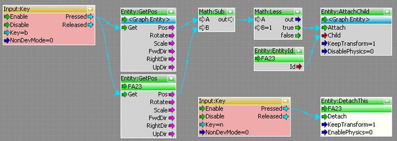
One has chosen to include the ‘Entity:AttachChild’ flow graph node within experiment two due to its potential efficiency in achieving aspects of my overall porosity lens concept. Most importantly, this node, as well as its associated sibling node, ‘Entity:DetachThis’ will allow for me attach and detach various entities within the flow graph simultaneously in order to portray a systematic approach and hence interaction within an environment through the town hall station prefab regarding the protagonist. Through experimentation with this node it is clear that I will be able to achieve this aspect of the experiment through such a node, once further developing and exploring a manner in which to attach entities within a specific location.

Detailed Node Research:
The Entity:AttachChild flow graph node belongs to the Entity family and is most commonly used in association with the ‘Entity:DetachThis’ node to attach and detach entities together within a Crysis environment through the flow graph scripting system. This particular node consists of only inputs, including ‘Boolean’, ‘entity’ and ‘any’ expressions, slightly similar to the DetachThis node which also consists of only inputs without any outputs. We are able to break this node down further to identify the purpose of each input to hence gain a better understanding of its purpose within the flow graph system and its potential implementations within our experiment.

- Entity Id Port : This component defines the entity which will be attached, hence the ‘child’ of a ‘parent’ entity (defined through an ‘Entity:EntityId’ node).

- Attach Port : This component provides the trigger of the attached entity, through such as an input key.

- Child Port : This component provides the entry port to define the child attachment, hence the connection between the ‘parent’ and the ‘child’ entities.

- Keep Transform Port : This component is a Boolean expression which defines whether the child entity will remain in the same transformation within the world space of the environment.

- Disable Physics Port : This component allows one to by force to disable the physics upon a child entity when attaching.

Note: All the above components of the AttachChild entity have no default values.

Source: http://wiki.crymod.com/index.php/FGNode:Entity:AttachChild Accessed: September 16, 2010.

2. Entity:EntityPos –

Reason for Implementation within Experiment Two:

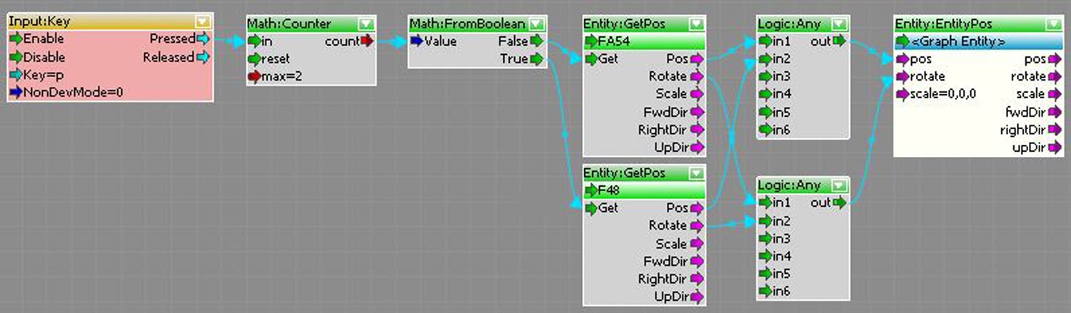
I have decided to implement the Entity: EntityPos flow graph node within experiment two due to its capabilities in achieving the required resultant of my porosity lens. Through initial research I have discovered that this node will be utilised in allowing an entity to rotate upon the player’s movement within the game. Such will allow for one to gain the position of an entity before then using a vector family node to receive and actable upon notion, such as subtracting two positions to rotate the entity. This entity portrays such potential due to the manner in which it has the ability to alter an entities position, rotation or scale while also identifying this information, hence making it an ideal node to be used to the sourcing and rotation of the town hall prefab sections within my porosity lens. Finally it will allow me to generally control the individual cubes with precision and accuracy in terms of world co-ordinates and rotation.

Detailed Node Research:

The flow graph node in the form of ‘Entity:EntityPos’ is part of Entity category, portraying quite a diverse system of entity influences regarding vector movements such as positioning, rotation and scaling. This particular node consists of various inputs and outputs of mainly the ‘vector’ and ‘entity’ expression allowing for such to work in association with the Vector3 category nodes. The node initially contains empty default values, or simply zeroed out vector values such as (0,0,0). To further develop ones understanding of this node, I have researched the nature of each individual input and output component for future implementation reference.

- Entity Id Port : This input defines the entity within the environment which will be altered through the settings defined within the components of this node.


- Pos Port (Input) : This input component refers to the global position of the entity within world space in terms of a vector3 expression.


- Rotate Port (Input) : This input defines the rotational movement of the selected and defined entity in terms of the three rotational axes, with regards to a rotation velocity defined by degrees per second.


- Scale Port¬ (Input) : This input may be used to define a scale extension or subtraction regarding vector3 axes.


- Pos Port (Output) : This output refers to the resultant action define by the position input in terms of a vector or vector modification such as subtraction.


- Rotate Port (Output) : This output defines the rotation resultant of the identified input, with reference to a vector such as multiplication.


- Scale Port (Output) : This output component refers to the resultant vector action of the scale input in terms of an additional influence such as the inversing of the vectors axes.


- Fwd Dir Port : This output within the node allows for the restriction of a defined input with reference to the Y axis in terms of positioning, rotation or scaling.


- Right Dir Port¬¬ : This particular output defines the resultant of an input component with regards to only the X axis.


- Up Dir Port : This output refers to the vector input influence of a component regarding the defined entity within the world space along the Z axis.


Source: http://wiki.crymod.com/index.php/FGNode:Entity:EntityPos Accessed: September 16, 2010.


3. Entity:GetPos -


Reasons for Implementation within Experiment Two:

I have decided to include the ‘Entity:GetPos’ flow graph node within experiment two due to the potential power and ability it will provide me in achieving my porosity lens concept. This particular node will work in conjunction with the other nodes I have selected such as Entity: EntityPos, as I have discussed there, in for example identifying the world position and particular rotation of an entity (perhaps an individual cube) before then comparing it to another to determine whether an action is carried out. Further more such will allow for the completion of such aspects as perhaps determining whether a individual cube or piece of the station is within a position upon a face to determine whether to attach those numerous cubes together into a single face for rotation.

Detailed Node Research:

This particular node belongs to entity family of flow graph nodes and is comprised of various inputs and outputs to determine critical and precise information regarding a particular defined entity. The Entity:GetPos node is interesting due to the manner in which it separates this information into mainly three aspects including Position, Scale, and Rotation, as well as furthers its direction upon the three axis. It is important to note that each output is of a ‘Vector’ nature, allowing for direct use of Vector nodes such as ‘Vec:Mul’ to in this case increase the value or direction. An excellent feature of this node is the manner in which the ‘Get’ input is able to be from any other flow graph output whether it is a Boolean and a simple input.

- Entity Id Port – This entity type input defines the entity which is to be used to hence gather information upon with reference to its direction, position, scale and rotation.

- Get Port – This any type input works as the trigger to define when the node will begin to process the information of the desired and defined entity.

- Pos Port – This output is a vector type, presenting the position of the defined entity within the games world co-ordinates.

- Rotate Port – This vector type output defines and presents the current rotation of the defined entity in terms of an angle upon any axis or combination.

- Scale Port – The scale output is a vector type which determines and conveys the scale of a defined entity within the level with reference to the various axis.

- FwdDir Port – This vector output simply portrays the direction of the defined entity upon specifically the y-axis.

- RightDir Port – This port is a vector type output, defining and conveying the direction and the entity upon specifically the x-axis.

- UpDir Port – This final vector type output defines the direction upon the z-axis of a defined entity to portray it in a manner for another input.

Source: http://wiki.crymod.com/index.php/FGNode:Entity:GetPos Accessed: September 16, 2010.

EXP 2: Week 1: Flow Graph Nodes Research

Within the current preliminary stage of research of Exp 2, I have produced a series of potential flow graph nodes which convey interesting prospects in general and in relation to my preliminary concept. Such a comprisal is outlined below:


1. EntityScreen (Plug-in) -

The ‘EntityScreen’ plug-in provides three additional nodes within the flow graph which allows one to control entities depending on their two dimensional position within the screen, in terms of x and y co-ordinates.
- Entity:EntityScreenPos
- Entity:GetEntityScreenPos
- Entity:EntityScreenText

Potential: This particular node system could potentially allow for rotation control of the various proposed individual cubes within planes through the camera’s view position. Such would allow for the structure to rotate while the responder’s perception remains dependant, allowing the environment to reform interconnecting the perception of the mentally unwell player and responder.


2. Iterators (Plug-in) -

The ‘Iterators’ plug-in includes four additional nodes allowing for the repetition of a flow graph process through numerous entities once originally created and defined.

- Iterator:GetEntitiesInSphere
- Iterator:GetEntitiesInBox
- Iterator:GetEntitiesInArea
- Iterator:GetEntities

Potential: Through this plug-in I identified a potential use within my own flow graphs in achieving my concept with reference to the systematic algorithms. Each algorithm is consisted of simple repeated rotations, which become rather complex within Crysis due to the grouping and un-grouping of the individual cubes into planes. However this plug-in may allow for such general rotation operations to be set as a singular unit, before being iterated when required.


3. Entity: EntityPos -

The ‘Entity:EntitiyPos’ flowgraph node allows for the manipulation of an entity within the environment through the altering of its position, scale or rotation in terms of vectors.

Potential: The potential for this node is immense due to the significance of the rotation feature within the proposed concept. Such a node could allow for the control of numerous individual cubes or a plane through various additional interaction possibilities such as the players position or other entities.


4. Entity: AttachChild -

The ‘Entity:AttachChild’ node allows for the grouping of numerous entities within the environment, while working in association with the ‘Entitiy:DetachThis’ in the un-grouping of entities.

Potential: The significance of this nodes discovery allows for a solution to emerge with regards to the grouping and un-grouping aspect of the numerous individual cubes and hence planes within my experiments proposal. Through the incorporation of this node within the environment I will be able to begin considering the manner in which such a process will occur with regards to inputs, action filters or other interactive opportunities to enhance the overall purpose of the study.


5. Mouse (Plug-in) -

The ‘Mouse’ plug-in is one which is rather simple, conveying the mouses position within the screen as x and y co-ordinates while also identifying particular entities within game mode.

Potential: The potential for the mouse plug-in within my experiment exists within the rotational control of the individual cube planes in terms of controlling either the direction of the player from within the structure or the general rotation from the exterior by adding a mouse button handler, allowing for the responder to interact with the environment, controlling the ‘disorder’ experienced by the player or protagonist.


6. Xml (Plug-in) -

The ‘Xml’ plug-in simply refers to the importing and editing of Xml documents within the flow graph editor to customise nodes, as Xml represents the file format of flow graphs within Crysis.

Potential: Although the potential use of this plug-in is abstract and rather advance it remains to exist in the form of modifying flow graph set ups and nodes to maximise the efficiency within my experiment. With my own limited scripting experience, I feel as though I may be able to produce modifications to achieve aspects of my concept which would otherwise be un-achievable.

7. Entity: DetachThis -

The ‘Entity:DetachThis’ node works in association with the ‘Entity:AttachChild’ node as it allows one to detach an entity which has been attached within the flow graph within the overall Crysis Environment.

Potential: The potential significance of this node is immense as it will allow me to perform the required algorithms within experiment two, due to being able to detach entities which have been previously attached, to hence perform the next stage of the systematic approach. Due to the nature of its inputs one will able to consider the use of Boolean expressions with regards to altering the entities transformation and physics within world space.

8. Movement: RotateEntity -

The ‘Movement:RotateEntity’ node allows for one to define the rotational speed (defined through degrees per second) of an entity upon any axis within Crysis environment.

Potential: This particular node has great potential within my experiment as it may allow for me to rotate my entity planes of cubes while working in association with other nodes such as ‘Entity:AttachChild’. Through the variable options of defining the rotational axis, I will be able to specify in an easy manner the required rotation of each plane in association with the systematic algorithms. This will be enhanced through the ability to specify the rotation velocity within the one node component.

Sources:
- http://fgps.sourceforge.net/Help/plugins.html Accessed September 12, 2010.